
May 25, 2026
Digital Outputs in Home Security and Automation: Dry Contact vs. Open Collector
If you have spent any time wiring security sensors or home automation devices, you have probably heard the phrase “dry contact.” If you have dug into the installation manual for a Qolsys, DSC, or 2GIG panel, you may have also come across “open collector output” or “PGM output.” Both terms describe a category of electrical connection called a digital output, and understanding the difference between them will save you a lot of head-scratching when you are wiring things up at home.
This article is an introductory guide for technically curious homeowners and DIYers. You do not need an engineering background to follow along. The goal is to give you enough working knowledge to understand what these outputs do, which devices in the Alarm.com ecosystem use them, and how to choose the right output type for your application.
What Is a Digital Output?
To understand digital outputs, it helps to start with digital inputs, because they are two sides of the same coin. A digital input is a connection point on a security panel or device that reads the state of a sensor: is the contact open or closed? Is the circuit intact or broken? Wired door and window sensors, motion detectors, glass break sensors, and smoke detectors all connect to digital inputs on a panel. The panel is listening: when the circuit changes state, it knows something happened.
A digital output works the opposite way. Instead of reading a state from the outside world, it signals to the outside world. The panel or device closes or opens a circuit to tell something else to do something: turn on a siren, activate a relay, trigger a gate, reset a smoke detector circuit. The output drives something external, rather than sensing it. Most panels and expansion modules have both inputs and outputs, which is why you will see the abbreviation I/O (input/output) on device names like the DSC PGP-IO9.
Digital outputs are binary: they are in one of two states, on or off. Unlike a dimmer, which can produce a range of voltages, a digital output is either making a connection or it is not. That simplicity makes them extremely reliable and easy to work with, which is why they have been a staple of security and industrial control systems for decades.
In practice, digital outputs are used for two fundamentally different purposes, and it is worth understanding the distinction before getting into the wiring details. The first is signaling: sending a binary state to another device that is listening for it. A gate controller, garage door opener, or access control panel typically has a dedicated input terminal that expects a dry contact to close momentarily as a trigger. The relay or output is not switching any meaningful power here; it is just telling the other device to do something. The current involved is tiny. The second use is power switching: actually making or breaking the circuit that delivers power to a load. Turning a pool pump, fireplace, landscape light, or siren on and off by interrupting its power supply falls into this category. Here the relay has to handle the full voltage and current of the load, so matching the output’s ratings to the load matters a great deal. Keeping this distinction in mind will help you choose the right output type and the right product for whatever you are trying to accomplish.
The Two Most Common Digital Output Types
In the security and home automation world, you will almost always encounter one of two types of digital output: a dry contact or an open collector. They accomplish the same basic goal (signaling an on or off state) but they do it in very different ways, and the difference matters when you are choosing what to connect them to.
Dry Contact Outputs: The Simple Switch
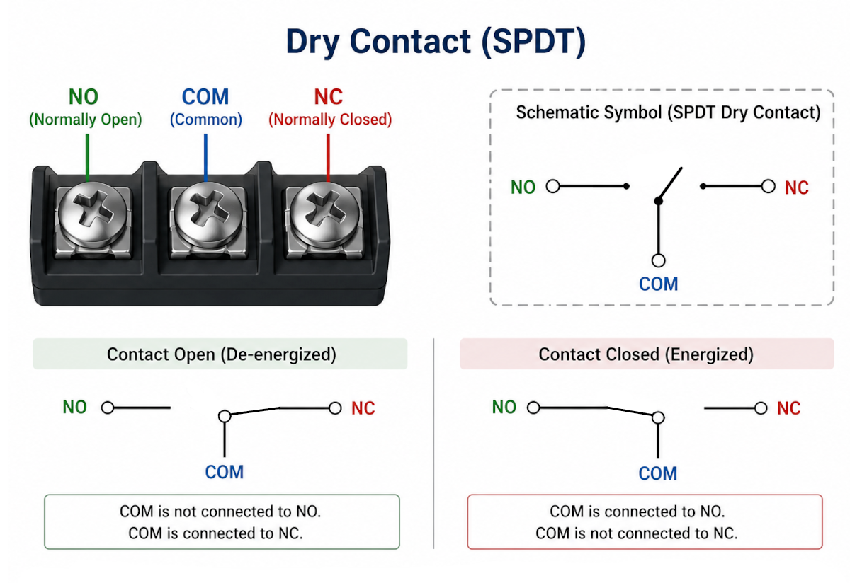
A dry contact is exactly what it sounds like: a pair of terminals that act like a simple mechanical switch. When the output is inactive, the switch is open (the two terminals are not connected to each other). When it is activated, the switch closes (the two terminals are connected). The word “dry” means the contact has no voltage of its own. It is just a pair of terminals that can make or break a connection. Whatever powers the circuit runs through those terminals is supplied entirely by the external device being controlled.
The opposite of a dry contact is a wet contact. A wet contact has voltage present on it. A common example is a thermostat: the furnace or air handler puts 24V AC on the thermostat wiring, and the thermostat switches that voltage to signal a call for heat or cooling. The voltage is built into the circuit itself. Dry contacts are generally safer and more flexible because the device driving the contact does not need to know or care what voltage the external system uses. The external system supplies its own power and just uses the dry contact as an on/off switch.
Think of it like a light switch. A standard wall switch does not generate its own electricity. It just interrupts or completes the power circuit that runs through it. A relay output on a Z-Wave switch works the same way: it is a small electromechanical or solid-state switch that opens and closes based on a command, and the power for whatever is being switched flows through it from an external source.
Dry Contact Voltage Ratings
Because the voltage in a dry contact circuit comes entirely from the external device, dry contacts are rated by how much voltage and current they can safely handle. You will commonly see two ranges in security and home automation products. Low voltage ratings cover circuits running at 12V to 24V DC or AC, which is the range used by most security panels, gate controllers, garage door operators, and low-voltage control lines. Line voltage ratings cover standard household power at 120V or 240V AC, which is the range used to switch lights, fans, HVAC equipment, and other household loads directly. Many smart relay products (like Zooz’s ZEN51 or ZEN52) are rated for line voltage and can switch standard 120V circuits directly inside a wall box, while others (like the Alarm.com Flex IO relay output) are rated only for low voltage and must never be connected to line voltage.
Always check the voltage and current rating of a dry contact before connecting it to anything. Exceeding the rating can damage the output, damage the device being controlled, or create a safety hazard. When in doubt, use a dry contact to control the coil of a relay (a low-voltage, low-current load) and let the relay’s heavier contacts switch the actual load.
Normally Open vs. Normally Closed
Most relay-based dry contact outputs have three terminals: Common (COM), Normally Open (NO), and Normally Closed (NC). The Common terminal is always connected. NO and NC describe what happens to the circuit at rest, before the relay is activated. A normally open contact is an open circuit (disconnected) when the relay is at rest, and closes when the relay is activated. A normally closed contact is a closed circuit (connected) when the relay is at rest, and opens when the relay is activated. Which terminal you wire to depends entirely on the behavior you want.
For most home automation applications, you will use the NO terminal. Controlling a gate, triggering a garage door, switching a pool pump, or activating a fireplace all follow the same logic: you want the circuit to be open by default and only complete it momentarily or while the relay is active. Wiring to the NO terminal gives you exactly that. The NC terminal is used when you need a circuit to remain complete until something triggers it to break, which is more common in fail-safe or supervisory applications. For example, a fail-safe door lock might be wired to NC so that it stays locked even if the relay loses power. Some Zooz relays, like the ZEN17, provide both NO and NC outputs on each channel, giving you the flexibility to choose the behavior that fits your application without having to add additional hardware.
Open Collector Outputs: The Transistor Switch
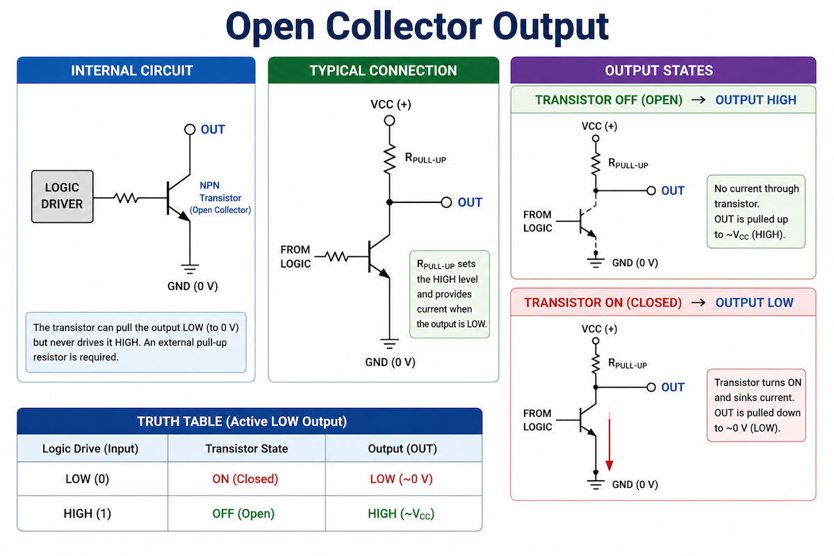
An open collector output is a different animal. Instead of a mechanical or electromechanical switch, it uses a transistor inside the device to pull a terminal down to ground (0V) when activated. When the output is inactive, the terminal is “floating,” meaning it is not connected to anything. When it is activated, the transistor turns on and the terminal is connected to ground.
The term “open collector” comes from the transistor’s physical structure. In an NPN bipolar transistor (the most common type used in these circuits), the collector is the terminal that pulls to ground when the transistor is on. When the output is inactive, that collector is left “open,” meaning unconnected. Hence: open collector.
How you wire an open collector output depends on whether you are signaling or power switching. For signaling applications, the device being triggered often has its own internal voltage present on its input terminal. You simply connect the open collector terminal to that input and a shared ground. When the output activates and pulls the terminal to ground, the receiving device sees the state change and responds. No external power supply is needed on your end. For power switching applications, you do need to supply the power yourself. One side of the load connects to a positive voltage (often the panel’s 12V auxiliary power output), and the other side connects to the open collector terminal. When the output activates, the transistor connects that terminal to ground, completing the circuit and powering the device. This is a common configuration in security panels: the panel provides auxiliary 12V power on separate terminals, and the open collector output acts as the “low side switch” by connecting the device’s negative lead to ground.
A useful way to picture this: the open collector output is like a switch that the panel can connect or disconnect to ground (the negative side of the power supply). The panel does not supply the positive power; it just controls the ground return. You supply the positive voltage from another source (like the panel’s 12V aux output), connect the device in between, and the open collector output controls whether the circuit is complete.
Open Collector vs. Open Drain
You may sometimes see the term “open drain” in device documentation. Open drain describes the same concept but applied to a MOSFET transistor (a different type of transistor commonly used in modern electronics and microcontrollers) instead of a bipolar transistor. In a MOSFET, the equivalent terminal is called the drain rather than the collector. Functionally, open drain outputs behave the same way as open collector outputs from a wiring standpoint: the output pulls to ground when active and floats when inactive. The distinction is an internal construction detail. For practical wiring purposes in the security world, open collector and open drain are treated identically. Open collector is the older and more common terminology in alarm system documentation, so that is the language you will see most often in DSC, Qolsys, and 2GIG installation manuals.
Open Collector Ratings
Open collector outputs are rated by the maximum voltage and current the transistor can handle without damage. Typical security panel open collector outputs are rated for low-voltage, low-current loads. For example, the PGP-IO9 outputs are rated up to 15V DC at 1A. You cannot connect line voltage (120V AC) directly to an open collector output. The transistor will be destroyed immediately. Open collector outputs are designed to drive small, low-voltage devices: a relay coil, a buzzer, an LED indicator, or a low-current solenoid. If you need to switch a larger or higher-voltage load, you use the open collector output to drive a relay, and the relay’s dry contact switches the actual load.
How to Test a Digital Output with a Multimeter
A multimeter (also called a volt-ohm meter) is the right tool to check the state of a digital output. The test procedure is essentially the same for both types: set your meter to ohms or continuity and check whether the output reads open or closed. The only difference is which terminals you place your probes on.
For a dry contact output, set your multimeter to the resistance (ohms) or continuity setting. With the output inactive, place your probes on the two dry contact terminals. You should see high resistance or an open circuit (no continuity). When the output is activated, you should see near-zero resistance or a continuity beep. This confirms the contact is opening and closing as expected. Some meters have a dedicated continuity mode with an audible beep, which is the fastest way to do this test.
For an open collector output, use the same approach: set your meter to ohms or continuity and place one probe on the output terminal and the other on the panel’s ground. When the output is inactive, the transistor is off and there is no path to ground, so you will read high resistance or an open circuit. When the output is activated, the transistor conducts and the PGM terminal is connected to ground, so you will read near-zero resistance. From the meter’s perspective, it behaves exactly like a dry contact: open when inactive, closed when active. The main practical difference is that on a dry contact you measure across the two contact terminals, while on an open collector you measure from the PGM terminal to ground.
Digital Output Devices in the Alarm.com Ecosystem
Now that the concepts are clear, here is a look at the specific devices you will encounter when building an Alarm.com system with digital output capability. They fall into two groups based on output type.
Open Collector Outputs: PGM Outputs on Security Panels
PGMs (Programmable Output Modules) are the DSC framework for open collector outputs, and they are only available on Qolsys and DSC systems. A PGM is a hardwired terminal on the panel or a wireless expansion module that is normally open (floating, not connected to ground) and pulls to ground when activated. You can program them on the panel itself to activate in response to an alarm or sensor event, on a timed basis, or with inverted or latching logic. When used with Alarm.com, PGM outputs require the appropriate service add-on: the Lights or Lights and Thermostat Bundle add-on for switch applications, or the Garage Door and Gate Control add-on for gate applications. There is also an important current limitation: as of this writing, PGM outputs cannot be included in Alarm.com automation rules, scenes, or schedules. They can only be activated from Alarm.com with a manual button press in the app or on the website. This has been a meaningful constraint compared to Z-Wave relays, but it is on its way out: Alarm.com is adding support for using PGM outputs in automation rules and schedules soon, which will close most of the gap between PGMs and Z-Wave relays for automated control. One caveat to note: this will apply to PGMs configured as switches, not to PGMs configured as gates. One thing PGMs do very well in Alarm.com is gate control: they can be configured as a self-closing gate that you open with a button tap in the app, which is a convenient and reliable setup for driveway gates.
PGM outputs are perfect for triggering a relay, powering a buzzer, controlling a low-power device, or any application where you need the panel to switch a small DC load on and off. The most common wiring approach is to supply 12V auxiliary power from the panel to one terminal of the device being driven, and connect the other terminal to the PGM. When the PGM activates, the circuit is complete and the device turns on. For a more detailed look at wiring and programming PGMs, see the Qolsys/DSC PGM Outputs guide on the Surety support forum.
Qolsys IQ Pro
The Qolsys IQ Pro is a professional-grade all-in-one panel with onboard PGM outputs. It is compatible with Alarm.com and supports up to 4 command output groups per partition. PGM support in Alarm.com requires IQ Pro software version 4.3.0n or newer.
Qolsys IQ Hardwire PowerG (PG9WLSHW8)
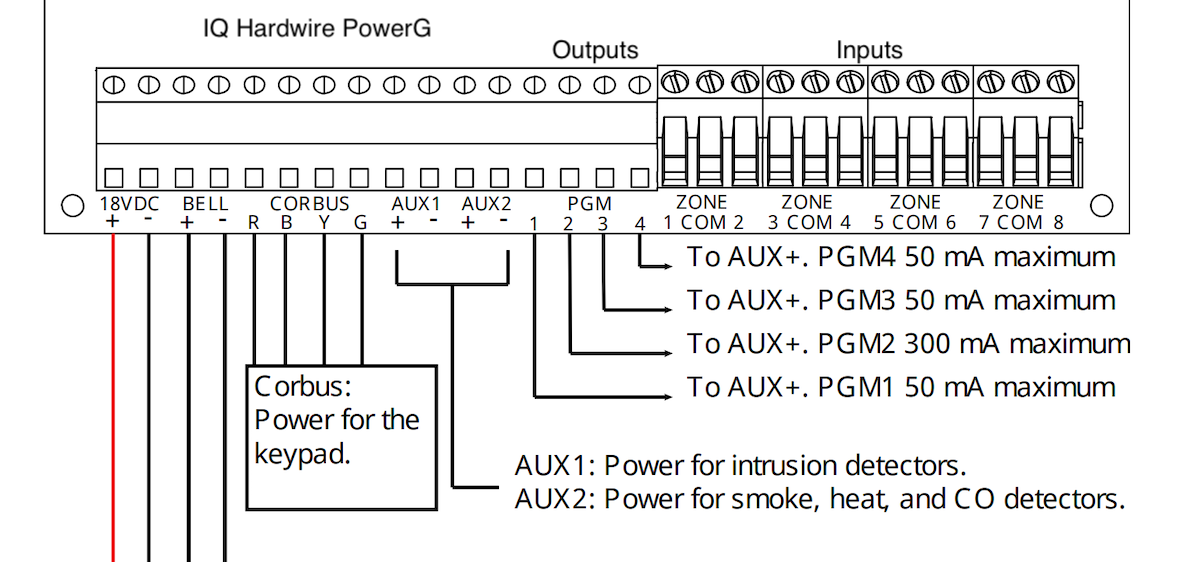
The IQ Hardwire PowerG is a hardwired zone expander that translates wired sensors into the wireless PowerG protocol so they can communicate with an IQ Panel 4 or IQ Panel 5. It also includes PGM output terminals, which means you can add open collector output capability to a panel that does not have onboard PGMs. Alarm.com PGM support on the IQ Panel 4 requires firmware 4.5.0 or newer and uses the Hardwire Translator as the output hardware.
DSC/Qolsys PowerG+ Input/Output Module (PGP-IO9)
The PGP-IO9 is a compact wireless module that communicates over the PowerG radio protocol. It can be configured for 4 hardwired inputs (zones) or 2 inputs plus 2 PGM outputs. Because it is wireless, you can place it anywhere within range of the panel without running wire all the way back to the panel, which makes it ideal for detached garages, outbuildings, or gate control locations. The outputs are rated up to 15V DC at 1A. The PGP-IO9 is supported on the IQ Panel 4 running firmware 4.6.1 or newer and on the IQ Panel 5. Its outputs are designed for devices with dry-contact control inputs or for driving external relay coils, not for direct connection to higher-voltage loads.
DSC PowerSeries Pro and PowerSeries Neo
DSC’s own panels, including the PowerSeries Pro and PowerSeries Neo, also have onboard PGM outputs. Since PGMs are a DSC framework, it is no surprise that DSC panels have native support for them. Both the PowerSeries Pro and PowerSeries Neo are compatible with Alarm.com, and their PGM outputs can be used for the same applications as those on Qolsys panels: gate control, relay triggering, low-voltage device switching, and more.
2GIG GC3 and GC3e / Edge Panels
2GIG panels, including the GC3, GC3e, and GC3 Edge, also include onboard open collector outputs that follow the same electrical principle as Qolsys/DSC PGMs: the terminal pulls to ground when activated and is floating when inactive. The key difference is that 2GIG’s outputs do not appear in Alarm.com at all. They are controlled and automated entirely at the local panel level, not through the Alarm.com app. In practice, they are most commonly used for triggering a wired siren when the alarm sounds, which the panel handles automatically without needing any cloud connectivity. If you need an output that is controllable and automatable through Alarm.com on a 2GIG system, a Z-Wave relay is the way to go.
Dry Contact Outputs: Z-Wave Relays and the Flex IO
Dry contact outputs are more commonly found in Z-Wave smart relay devices. These products are essentially smart switches with relay outputs. They receive Z-Wave commands from your Alarm.com system and close or open a dry contact in response. Because the contact is dry, it does not matter (within the relay’s rating) what voltage and current the external device needs. The relay handles it. This gives you enormous flexibility for switching everything from low-voltage control circuits to 120V or 240V loads, depending on the specific relay model. Z-Wave relays also have a significant advantage over hardwired PGM outputs when it comes to Alarm.com integration: they appear in the app as a standard light switch and can be fully used in automation rules, scenes, and schedules. If you want an output that you can automate (turn on at sunset, trigger when the alarm arms, run on a daily schedule), a Z-Wave relay is currently the better choice over a PGM output for that purpose.
Zooz Smart Relays
Zooz makes one of the strongest lineups of Z-Wave relay products available, and multiple models have been verified working with Qolsys IQ Panel 4 and Alarm.com by community members on the Surety unofficial Z-Wave device compatibility list. The full Zooz smart relay lineup is available at getzooz.com/smart-relays. Key models to know about are covered below.
| Model | Channels | Max Load | Z-Wave LR | Best For |
|---|---|---|---|---|
| ZEN51 Single Relay | 1 | 10A, 120V AC | No | Single light or load behind a switch |
| ZEN52 Double Relay | 2 | 120V AC each | No | Fan/light combination, two independent loads |
| ZEN16 MultiRelay | 3 NO outputs | 20A / 15A / 15A | No | Sprinklers, landscape lights, multi-output control |
| ZEN17 Universal Relay | 2 NO/NC outputs | 20A / 10A | No | Gate controllers, low-voltage control lines, two-output installs |
| ZEN57 XS Relay | 1 | 5A, 240V | Yes (800LR) | Compact install at distance from panel |
| ZEN58 LV XS Relay | 1 | 3A, 0-240V | Yes (800LR) | Gate and garage openers at range, 9-40V powered installs |
| ZEN78 High Power Relay | 1 | 40A, 120/240V | Yes (800LR) | Pool equipment, EV chargers, heated driveways at range |
Before reaching for a generic Z-Wave relay, it is worth checking whether Alarm.com already has a purpose-built solution for what you are trying to do, because those integrations will almost always give you a better experience. For garage doors, a dedicated Z-Wave garage door controller like the Ecolink GDZW7-LR shows up in Alarm.com as an actual garage door with proper open/close status, rather than a plain light switch toggle. For driveway gate control, PGM outputs and the Alarm.com Flex IO are both purpose-built solutions: either can be configured to appear as a self-closing gate in the app with a dedicated gate button. The Flex IO is particularly well-suited for gates that are far from the home where running a wire back to the panel is not practical, since it connects over cellular and can be mounted outdoors. The catch with both options is the automation limitation: if you want to automate the gate (open at a scheduled time, trigger based on an event), a Z-Wave relay is currently the only way to do that through Alarm.com. For irrigation, Alarm.com has direct native integrations with Rain Bird, Rachio, and Hunter systems, so if you have one of those brands you are better served by their dedicated integration than by a generic relay. For thermostats and HVAC, Alarm.com has strong native support for a wide range of thermostats, so a Z-Wave relay is generally not the right tool there either.
Where Z-Wave relays shine is in applications that do not have a purpose-built Alarm.com integration: pool pumps, gas or electric fireplaces, landscape lighting, irrigation systems not supported by Alarm.com’s native integrations, and any other on/off load where you want app control and automation without a dedicated smart device. The ZEN78 High Power Relay (40A, 120/240V) is particularly well-suited for pool equipment and other high-current loads. For a fireplace or other moderate line-voltage load, the ZEN51 or ZEN52 are straightforward choices.
The ZEN16 MultiRelay provides 3 independently switchable dry contact outputs in one unit, each with its own input monitoring terminal, making it a good option when you need multiple outputs from a single device. The ZEN58 LV XS Relay is well-suited to driveway gate applications because it runs on a 9-40V power supply (often available at the gate controller itself) and provides a dry contact output that can be wired directly to the gate’s control input. Community member testing has confirmed the ZEN52, ZEN16, ZEN58, and ZEN78 all working properly in Alarm.com via the Qolsys IQ Panel 4.
For installations where the relay will be at a significant distance from the panel, such as a gate at the end of a driveway, the ZEN57, ZEN58, and ZEN78 are the better choices because they support Z-Wave Long Range (800LR). Z-Wave Long Range uses a different radio mode that dramatically extends the communication distance compared to standard Z-Wave mesh, making it far more reliable for devices that are far from the panel or separated by walls and other obstructions. One important detail: to take advantage of Long Range on a Qolsys panel, the device must be enrolled using Smart Start rather than traditional inclusion mode. Traditional inclusion uses the standard Z-Wave mesh protocol and will not activate Long Range even on a device that supports it. Smart Start (which uses a QR code or DSK printed on the device) enrolls the relay in Long Range mode automatically when the panel detects it is a Long Range capable device.
Shelly Wave Relays
Shelly’s Z-Wave product line includes compact relay modules that have also been verified working with the Qolsys IQ Panel 4 and Alarm.com. The Shelly Wave 1 is a single-channel dry contact relay, and the Shelly Wave 1PM adds energy monitoring. Both devices are small enough to fit behind a light switch or inside a junction box, and the 1PM’s power monitoring capability shows up correctly in the Alarm.com app. Shelly’s Z-Wave relay lineup is available at us.shelly.com.
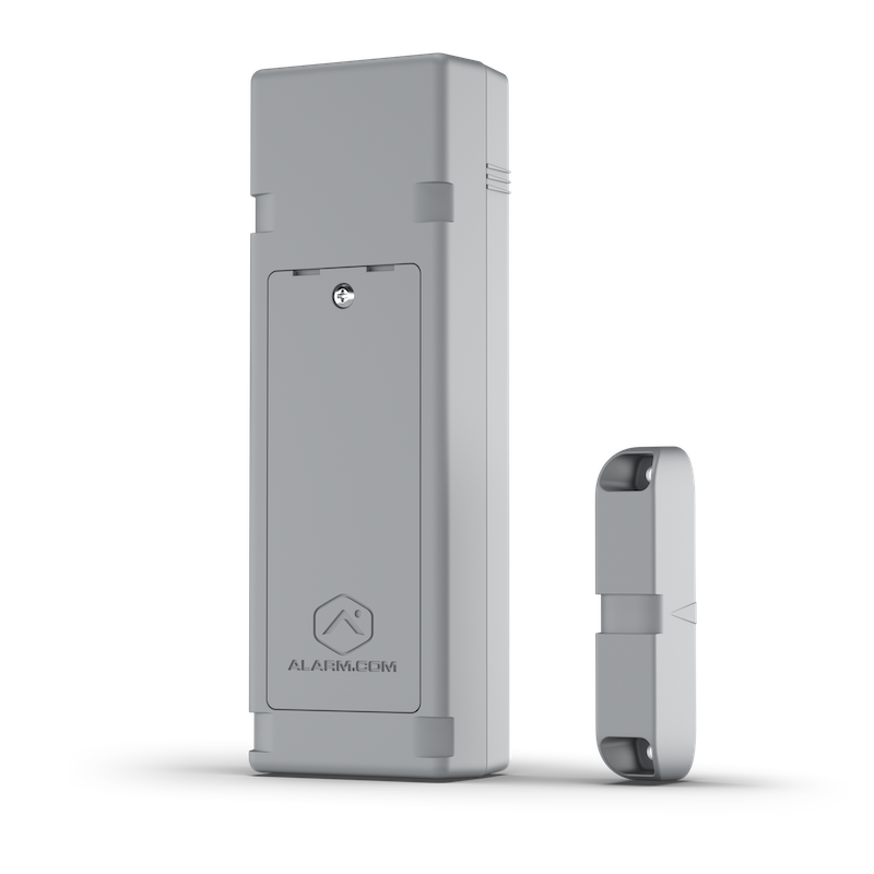
Alarm.com Flex IO (ADC-FLEX-100)
The Alarm.com Flex IO is a standalone 4G LTE cellular sensor that can operate independently of any security panel. It is primarily a contact sensor (with three built-in reed switch positions and a wired loop input), but it also includes an onboard relay output that provides a dry contact. This makes it useful for controlling a gate, garage door, or other low-voltage device at a remote location that has cellular coverage but no panel nearby, like a detached storage unit, a barn, or a vacation property gate.
There are important limitations to be aware of. The Flex IO relay output requires external DC power to the device (it cannot run on battery when the relay is enabled). The relay is rated for up to 24V AC or DC at a maximum of 40 mA. It is designed exclusively for control lines and dry contact applications. It must never be connected directly to control an electrical load. Doing so will damage the device. It is suitable for triggering a gate controller’s input terminal or a low-power solenoid coil, but you would need an additional relay if you wanted to switch a larger load. The Flex IO is available as an add-on to an existing Alarm.com account through Surety Home at $3.00 per month per device.
One practical advantage the Flex IO has over the PGP-IO9 and Z-Wave relays is its IP56 weather resistance rating, which means it can be mounted outdoors. The PGP-IO9 and Z-Wave relay modules are not rated for outdoor installation and must be mounted inside an enclosure or indoors, with a wire run out to the gate, garage door, or other outdoor device being controlled. If your gate controller or outdoor device is in a location where running wire to an indoor enclosure is not practical, the Flex IO’s ability to mount outdoors (and connect over cellular without any panel or Z-Wave network) makes it a uniquely flexible option.
Which Output Type Do You Need?
The right output type depends on what you are connecting and where the power comes from. Here is a practical framework for deciding.
Use an open collector PGM output when you are working with a wired device that accepts a low-voltage DC control signal and you are comfortable with the panel providing the ground path. Open collector outputs are well-suited for driving relay coils (to then switch a larger load), activating panel-connected sirens or buzzers, triggering a low-voltage lock release or solenoid, resetting a smoke detector circuit, and any application where the device being driven already has its own positive voltage supply and just needs a switched ground return. The Qolsys IQ Pro, IQ Hardwire PowerG, PGP-IO9, and 2GIG GC3/Edge panels all provide PGM outputs in this category.
Use a Z-Wave dry contact relay when you need to switch a circuit that supplies its own power independently, when the load runs at line voltage (120V or 240V AC), when the device being controlled has a dedicated “dry contact input” terminal (common on gate controllers, pool equipment, fireplaces, and audio/video equipment), when you need multiple independently switchable channels in a single device, or when you want to automate, schedule, or include the output in Alarm.com scenes. That last point is important: if you want the output to trigger automatically based on an event, run on a schedule, or be part of an Alarm.com scene, a Z-Wave relay is currently the most fully capable output type for all of that. PGM outputs and the Flex IO relay can be manually activated from the app today, but PGM automation is changing soon: Alarm.com is adding support for using PGM outputs in automation rules and schedules, which will make them a much stronger option for automated control.
| Application | Recommended Output Type | Example Device |
|---|---|---|
| Drive a relay coil from a panel PGM | Open collector | Qolsys IQ Pro PGM, PGP-IO9 |
| Self-closing gate (button in app, no automation needed) | Open collector (PGM) | Qolsys IQ Pro PGM, PGP-IO9 |
| Gate with automation (scheduled, event-triggered) | Dry contact (Z-Wave relay) | Zooz ZEN58 |
| Remote gate (button in app, no wire back to home) | Dry contact (cellular relay) | Alarm.com Flex IO |
| Switch a 120V light or fan | Dry contact (line voltage relay) | Zooz ZEN51, ZEN52 |
| Pool pump or spa equipment | Dry contact (high power relay) | Zooz ZEN78 |
| Gas or electric fireplace | Dry contact (line voltage relay) | Zooz ZEN51, ZEN52 |
| EV charger or 240V load | Dry contact (high power relay) | Zooz ZEN78 |
| Activate a siren or buzzer from the panel | Open collector | 2GIG GC3/Edge output, IQ Pro PGM |
Converting an Open Collector Output to a Dry Contact
There are two common situations where you need to convert a PGM open collector output to a dry contact. The first is when the device you want to control expects a dry contact input, such as third-party access control systems, audio/video equipment, or other devices with isolated dry contact inputs. The second is when you want to switch a load whose voltage or current exceeds the PGM’s ratings. PGM outputs are designed for small, low-voltage DC loads, so if you need to switch a higher-voltage or higher-current device, you cannot connect it directly to the PGM without risking damage. In both cases, the fix is the same: a small relay board that sits between the PGM and the target device. The PGM drives the relay coil (a low-voltage, low-current load that open collector outputs handle easily), and the relay’s isolated dry contact output connects to whatever the external device needs.
Two Altronix relay boards commonly used for this conversion in the security world are the RBSNTTL and the RB5. They both provide an isolated dry contact output, but they differ in their trigger voltage requirements. The RB5 is a DPDT relay board with 5A contacts rated for a 6-12VDC trigger input, so it needs at least 6V to energize. The RBSNTTL is an ultra-sensitive relay module that can be triggered by much lower voltages, down to TTL levels (3.3-5V), and can also handle 12V, making it more flexible. The right choice comes down to what power is available at the installation location. If you have 12V auxiliary power on hand, either board works. If you are working at a remote location, such as a PGP-IO9 installation where only a 5V supply is available nearby, the RBSNTTL is the one you need since the RB5’s 6V minimum would not be met. Both boards accept the trigger signal on one side and provide isolated dry contacts on the other, letting you deliver a clean dry contact to whatever device you are integrating without any risk of voltage or current mismatches damaging the panel output or the receiving device.
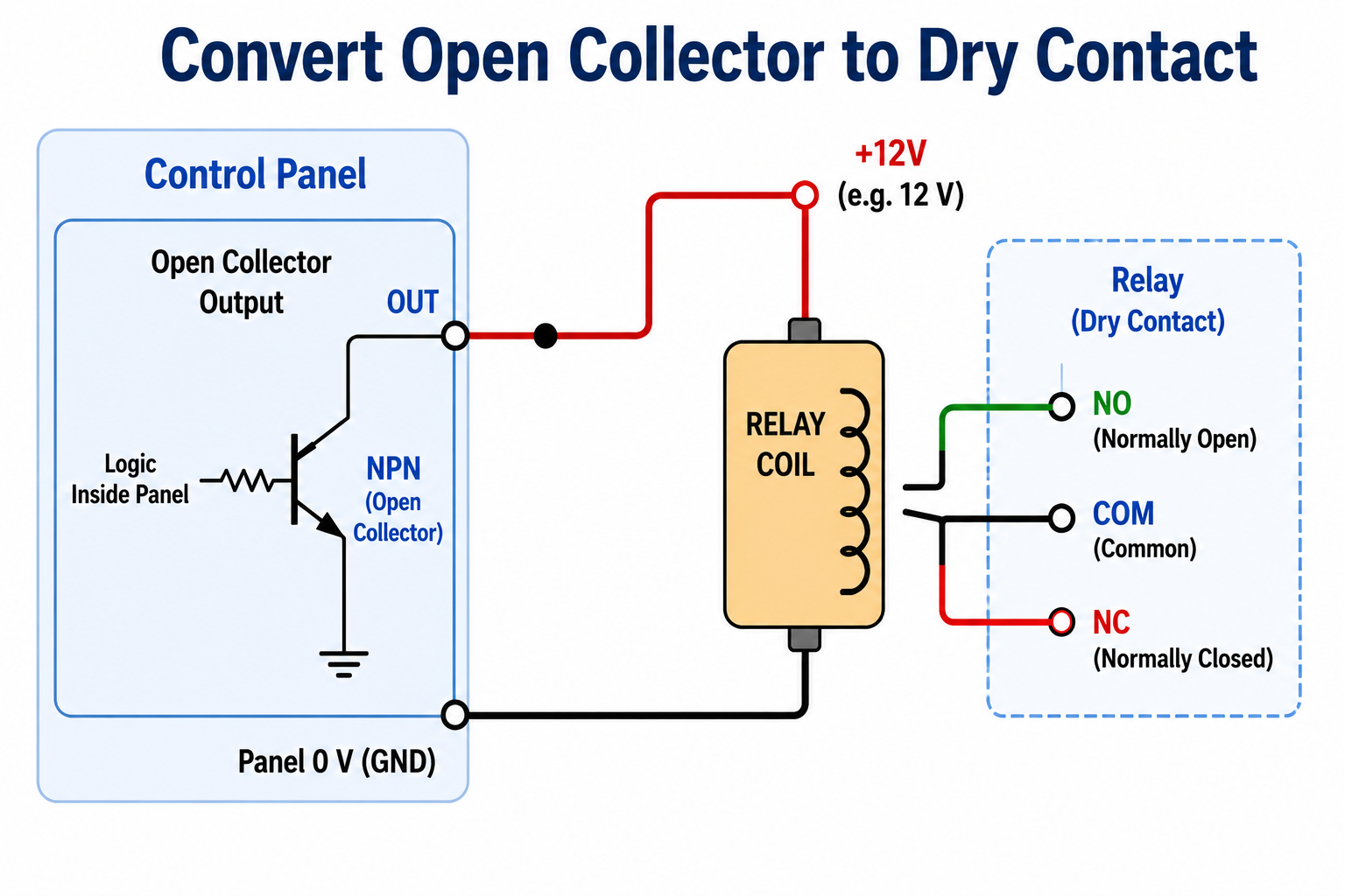
The same principle applies when building any relay-based circuit: an open collector PGM is an excellent driver for a relay coil. Use the PGM to activate the relay, and let the relay’s dry contact handle the actual load switching. This keeps the panel’s transistor output well within its current and voltage ratings while giving you the flexibility to switch almost any load the relay is rated for.
Putting It All Together
Digital outputs are the signaling side of a security and automation system. While inputs listen to the world (is the door open? did motion trigger?), outputs speak to it (open the gate, activate the relay, reset the smoke circuit). The two types you will encounter most often are dry contacts, which act like a plain mechanical switch and work with the external circuit’s own power source, and open collector outputs, which pull a terminal to ground and need you to supply the positive voltage for whatever is being driven.
In the Alarm.com ecosystem, open collector PGM outputs are built into panels and expansion modules like the Qolsys IQ Pro, the IQ Hardwire PowerG, the PGP-IO9, and 2GIG panels. Dry contact outputs are provided by Z-Wave smart relays like the Zooz and Shelly lineups, and by the Alarm.com Flex IO for cellular-connected remote locations. Understanding which type you have and what it can safely drive is the foundation for any reliable integration between your security system and the rest of your home’s devices.
Frequently Asked Questions
What is the difference between a dry contact and a relay output? A relay output is a type of dry contact. When people say “relay output,” they are usually referring to the output of an electromechanical or solid-state relay, which provides an isolated dry contact that makes or breaks a circuit. The terms are often used interchangeably in product documentation, but technically a dry contact is the broader category and a relay is one common way to implement it.
Can I connect an open collector PGM output directly to a 120V circuit? No. This would immediately destroy the transistor in the PGM output and could create a serious safety hazard. Open collector outputs are rated for low-voltage DC loads only, typically 12-15V at under 1A. If you need to switch a 120V load from a PGM, use the PGM to drive a relay, such as the Altronix RBSNTTL or RB5, and use the relay’s dry contacts to switch the 120V circuit.
How many PGM outputs does an Alarm.com system support? Alarm.com limits each partition to a maximum of 4 command output groups. Each PGM output is assigned to one of these groups. The physical number of output terminals depends on the panel and any expansion modules installed. Adding a PGP-IO9 or IQ Hardwire PowerG module increases the number of available output terminals without consuming the main panel’s onboard PGMs.
Do PGM outputs work in Alarm.com automations and scenes? As of the time of this writing, PGM outputs in Alarm.com can be controlled manually from the app (as a switch or gate) but cannot yet be included in automation rules, scenes, or schedules. They can be programmed on the panel itself to respond to alarm events, but app-based automation and scheduling are not available just yet. That is changing soon: Alarm.com is adding support for using PGM outputs in automation rules and schedules, which will let you trigger them on a schedule or as part of an automation rather than only by hand. Note that this applies to PGMs configured as switches, not to PGMs configured as gates. In the meantime, if you need that kind of control today, a Z-Wave relay shows up in Alarm.com as a light switch and already has full support for automation rules, scenes, and schedules.
What is the easiest dry contact relay to add to an Alarm.com system? For most homeowners, a Zooz Z-Wave relay is the easiest path. The ZEN51 (single channel, 120V) and ZEN52 (dual channel, 120V) are compact, pair easily with Qolsys and 2GIG panels, and show up as standard switches in the Alarm.com app. All of the Zooz relays mentioned in this article have been tested and confirmed working by real Alarm.com users in the Surety community.
What does “normally open” vs. “normally closed” mean for a relay output? These terms describe the default state of the relay’s contacts when no power is applied. A normally open (NO) contact is open (disconnected) when the relay is at rest and closes when the relay is activated. A normally closed (NC) contact is closed (connected) when the relay is at rest and opens when activated. Most automation applications use normally open contacts, because the circuit only completes when you want it to. Normally closed contacts are useful for applications where you want the circuit to remain complete until you break it, such as a supervised loop or a fail-safe lock.
