Need help wiring a aeotec microswitch. The light switch on the left is the one I’m wanting to hook up. I can get power the the microswitch but can not get the sixth to power the light. Need help.
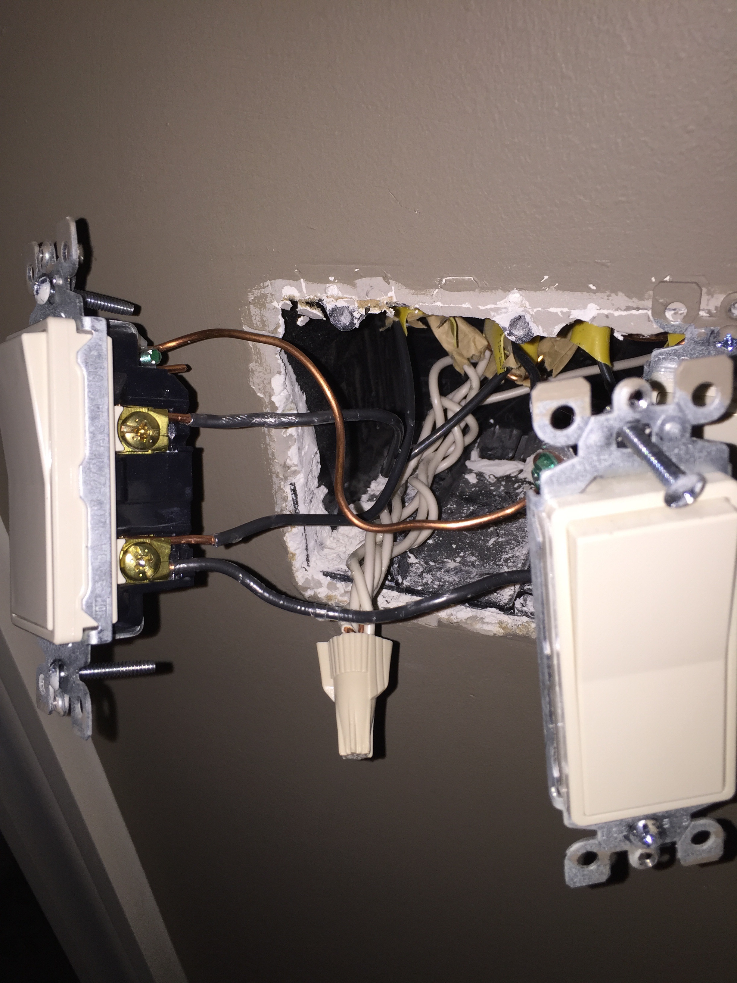
The white neutral…Pigtail off that wirenut with 14 gauge solid.

Line: 120v (live/hot black wire)
Load: other two black wires (wired same terminal)
White neutral
Ground: bare wire
Aeotec wiring

You need a meter. They have them at lowed for $11
Remove all wires from current switch, meter wires. You should see three black, a ground, and white (usually wire nutted)
120v black goes to line, other two go to load, ground/bare wire to green screw, and you may need a short peice of 14 guage solid to pigtail off the neutral wire nut.

I used a $34 lowes (GE/Jasco) zwave switch… much easier. To me the micro switches are only ideal if you have custom switches, or old fashioned toggles.

This is for wiring a 3way…(its for the Lowes GE/Jasco zwave, but the wiring aspect is same as far as determining which wires are which)
For three ways, remove all wires from both switches, meter all, one should be hot (120v) this is the primary switch ‘line’. You should see two black, one red, ground, and white (usually wire nutted)
Mark black wire that is hot (this is the common)
For main switch at 120v wire:
120v wire goes to line, red goes to traveler, other black to load, ground/bare to ground screw, use a short 14 guage white wire to pigtail off white wire nut, this goes to neutral.
On aux switch:
Meter, with main switch on, then when off, two should be hot- one when on, one when off (both travelers- usually one black and one red), one wire will have no voltage in either switch position.
Mark wire that is not hot in either switch position (this is the secondary/aux common)
Red to traveler (color isn’t really important, BUT the traveler MUST be the same wire at each switch), white pigtail to neutral, ground/bare to green wire nut. (The other two get wire nutted together, these will not be used)
For aeotec to switch wiring schematics see:
2-Way or Momentary Switch Wiring Schematic Without Live Wiring: Attaching a 2-way switch or a momentary switch is very simple. Just connect 2 wires to the 2-way or momentary switch then connect the 2 wires (doesn’t matter which way) to the 2 terminals next to the 3V terminal.

BE CAREFUL WITH CONNECTION OF LIVE (HOT) WIRE. If you connect it wrong to the aeotec micro switch, you will fry it.
Are you still having issues with installation? Is this a single switch circuit or is it a 3-way?
Jason it’s just a single pole but I have not been able to get it to work yet.
Please post a photo of your wiring if you currently have the micro switch wired up.
As stated above, you will need to determine which wire is line voltage. Have you done this?
Given the relatively strange 3rd wire connected you also need to determine if it indeed is a separate load wire or if it is intended to pass line voltage to another switch. Stranger things have been done. You will want to label them with electrical tape so you don’t lose track of which wires were connected to which switch terminal. Then meter them out.
So, questions to answer:
- Which conductor is 120?
- Was this 120 conductor wired with the 3rd conductor or by itself on the original switch?
If you already connected the “live” 120 line, anywhere but where it is shown in diagram, you have most likely already fried the micro switch.
You will need three pieces of 14 gauge wire.
Meter all your wires!
Pigtail one off the neutral wire at wire nut (take off wire nut, add a forth wire approx. 12" long or so, screw the nut back on all four wires)


Connect line/live 120, neutral, and both load wires as shown. (Leave ground where it is).
Remove the line and load wires, and wire them directly to micro switch, like so (only ground should still be wired to regular switch). Wire the pigtailed neutral wire as shown to micro switch.
Where the line and load wires were on regular light switch, you will now add the two other 14 gauge wires, and connect as shown to micro switch

14 gauge wires will not fit in the terminals labeled wall switch. They are intended only to connect to the common and switched terminals on your original 1-way wall switch. You are best to use two short 18 gauge wires to do so. These also have nothing to do with line or load.
So, the two short wires from micro switch need to be 18, and you are saying they do not wire back to where the line and load originally was on the regular switch?
intended only to connect to the common and switched terminals on your original 1-way wall switch
These also have nothing to do with line or load.
Please correct me if I am wrong, but “common” is the 120v Line on a single switch

In a 1-way switch configuration, yes, those two terminals are wired to where line and load were previously wired on the original switch, but no longer carry high voltage or directly connect to load. I just do not want these to be confused based on the drawing.
Also, it cannot be assumed that two of those wires are load wires directly. It would need to be metered out prior to any wiring instructions (other than tying in neutral).
Right.
He needs to meter. He should not be connecting wires if he is not metering them first.
The live wire is the one by itself on the switch. The other wires: one goes to the switch beside it and the other is load
The other wires: one goes to the switch beside it and the other is load
I have a new construction home, ditto for you. Mine is wired same.
With power on, meter both of those wires, both should not be hot. Connect them both to load on the micro switch. Wire you hot common/line/live 120, and neutral to micro.
The micro is now acting as load for anything that was previously connected to the wall switch.
Wire two wires where the load and line wires were on wall switch directly to micro as shown.
The wall switch is low voltage now, powered off micro.
What exactly does the switch beside it control? Correct me if I am not seeing something here, but with that set-up you have two switches that are in a broken 3-way configuration. One switch cannot be turned on unless the one next to it is turned on. Or, conversely, if that other switch is also wired to line voltage, both switches side by side would just control the same light.
Can you post a photo of how you had the aeotec micro switch wired?
When you have it wired up as shown in the diagram above, if you press the button on the face of the micro switch, does it change the light’s state? Does flipping the original switch change the light’s state? Which does not work, or do neither work?
I’m at work so don’t have a picture of the wiring. I will take one tonight.
I have live going to live on micro the other two wires going to load and load on micro. Then I have a neutral wire pigtailed to the other neutrals into the neutral on micro.
The switch beside controls a different light in bathroom.
Pressing the button on the microswitch doesn’t change anything. The light on the micro stays on and nothing changes, the lights stay off.
Flipping the light switch doesn’t change anything.
I can try a different microswitch tonight. Just to see if the switch is bad.
My wiring is same in my zwave switch. Make sure all connections are good (especially the neutral, check the wire nut)
Two black to load
One black to line (common/hot/live 120)
White pigtailed off nut to neutral
Bare to ground

...Pressing the button on the microswitch doesn’t change anything. The light on the micro stays on and nothing changes, the lights stay off. Flipping the light switch doesn’t change anything.
Just curious… did you at anytime connect/insert the 120v (hot) common/line wire into more than one connection of the micro?
Are you using a meter?
You really, really need to meter all three black wires, and make sure only one is hot.
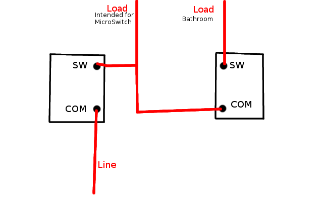
If these are both 1-way switches, then based on what was said by OP (one of the two conductors goes to load, one to the other switch in the gang box), you would have this:
Left switch controls lights intended for microswitch, and whether or not bathroom switch has line voltage at all.
Right switch only controls bathroom lights if other switch is on.
OR
If an additional line voltage conductor is connected to the right switch, Left switch controls lights intended for microswitch, and right hand switch controls bathroom lights and lights intended for microswitch regardless if the left switch is turned on.
If both switches currently control lights independently then the description given is incorrect and needs tested again.
So, before any other testing, can you verify that both switches operate their respective lights independently of one another, and verify that one of those wires pictured is simply a jumper from one switch in the gang box to the other?
Not that I know of. I will get a meter and test tonight. Could be more than one hot or just not a good connection with neutral.